Saturday, January 29, 2011

Session 4 - Flashing LEDs in different patterns

We are going to dig out some simple logics out of all these complexities of programming syntaxes, otherwise called grammar of programming language.  At this moment let us stop the study of grammar for a while.  It is possible to implement different types of logics within the knowledge of last three sessions.  In this session let us try to use the commands which we have already learned, to implement different tasks.
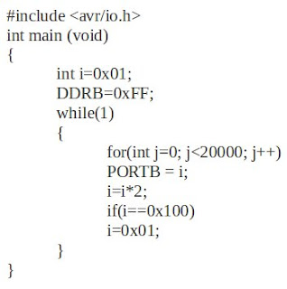
We often see flashing of LEDs in a series which give an effect of running light from one LED to other, when it is kept in a line.  The program below realizes this task.  It needs only a different logic with no new commands other than we discussed.  Now let us think about the logic working behind this program.


Here we are using a property of binary numbers.  The series given below gives the basic idea.


In the 'Result' part we can see the position of '1' is transfered to the left by a single bit position, in adjacent steps.  In the 'Process' part result of the above process is multiplied with '2' to find the new result.  It is logical to represent the whole calculations through the following equation.

i=i*2      where 'i' is an integer variable

The value of 'i' is updated each time the statement executes.

Now let us think about the real situation with LEDs.  Consider the 8 bits in the 'Result' part represent the data in 8 pins of B Port, which is connected to 8 LEDs.  It is interesting to see that the output obtained now was our aim.

Now going back to the logic part.  Since 'i' is an integer variable, its value will increase greater than 0b10000000, if the process continues.  But we have only 8 LEDs connected.  So if the value reaches 0b10000000, it needs to be reset to 0b00000001 to restart the operation.  Thus LEDs will flash continuously.

It is time to think about program coding.  The value of variable 'i' (declared as integer) is set to '1' initially.  There is no need to discuss about the functioning of each statement since we are familiar with all of them in previous sessions.
Here also a 'for loop' is used to obtain the desired delay in between flashing of each LEDs.  Since the value of 'i' represent the Result part in the series, 'i' is directly copied to PORTB.  Because Result part is the desired output.  After having the desired delay, value of 'i' is updated through the equation: i=ix2.  An 'if condition' is given to limit the value of 'i'.  When 'i' reaches 0b10000000, it is reset to 0b00000001 which enables the program to work from the beginning of the cycle.

Many kinds of logics can be developed like this to make different patterns.  Another program producing a different pattern is given below.  The changes in this program from the previous program are colored red.  Readers can dig into it and find the output.


As my friend asked last day, Is blinking LED is the only function of these costly microcontrollers?  The answer is a big 'no' with a small 'yes'.  The matter of fact is that microcontrollers can only generate these kind of small signals having a voltage ranging around 5V with a little mA current.  We need additional circuit arrangements to do other physical needs.

For example, if we need to drive a motor, we need a motor driving circuit.  This circuit is fed by the microcontroller signal to know the rotating direction of motor.  The power for driving the motor is given to the circuit separately.  Now we can understand the functioning of a fully automatic washing machine.  Its different motors are rotated at different timings, at different speeds and at different directions.  All these functions are controlled by processors and hence we say it has 'artificial intelligence'.  We can compare our processor to the brain of a human body.  It produces signals to organs and physical work is done by the organs.  However the possibilities of AVR microcontrollers are beyond limits.  It gives many more facilities in a ready-made package to make the programming simpler.  Let us discuss about them in the upcoming sessions.
Tuesday, January 4, 2011

Session 3 - Automatic blinking LEDs

We are going to achieve something more interesting in this session.  In the first session, the blinking of LED was out of our control.  In the second one, it was in control of switches.  Now controlled, automated switching is going to happen.  Here no need to connect any switches as in the previous case.  Just connect all the pins of B Port to 8 LEDs.  The aim of this session is to prepare a program which can make the LEDs blink automatically for a nominal time interval.  The following program does this job:


Most of the commands in this program are familiar through the previous sessions.  A new comer is the 'for' loop. 'For loop' is a very effective looping tool which can be used in variety of situations.  Here we have used this loop to acquire a delay between the blinking of LEDs.  Let us discuss how this task is accomplished by 'for' loop.  The syntax of 'for' loop is a little lengthy.  It looks like shown below:

From the first look, we can see a control variable named 'j' as main actor in this loop.  Inside the 'for loop', there are three parts.  The first one is familiar in the previous programs.  That is: 'int j=0'.  This statement assigns value '0' to the variable j.  The working of the loop depends on the value of this variable and so it is called the control variable.  The next part is the condition part.  Here it is 'j less than 20000'.  Compiler checks whether the value of the variable 'j' is less than 20000.  If it is true the statements written under the for loop statement will be executed.  (In this case, the value of 'j' is declared as zero.  So the condition is true).  Here the statement written under 'for loop' is PORTB=0x00;.  After executing this statement the third part of the 'for loop' statement will work out.  Here the third part is: 'j++'.  This statement tells the compiler to add one to the value of j.  That is, the statement PORTB=0x00 is executed once and the value of 'j' is incremented to '1' from '0'(0+1=1).  Then the condition is checked again (j less than 20000).  This cycle will repeat until the condition become false (Here when j=20000).

So let us think about the advantage of using this looping statement.  We could execute the statement PORTB=0x00 for 20,000 times without writing 20,000 commands!  We can include more than one statement below the for loop statement by using an opening and closing braces ({}), in the starting and ending of the statements below the 'for loop' statement.

Now let us come to our program.  Why do we need to execute the same command (PORTB=0x00) for 20,000 times?  When this statement is executed once, all the pins of 'B Port' will be in logic 0.  If we execute the statement 20,000 times repeatedly, there is no remarkable change in the output value.  Then why do we need to do this?  The answer is 'Delay'.
We may get a more clarified answer by looking at the next command.  It is another 'for loop' which executes the statement 'PORTB=0xFF'.  When this statement is executed, all the pins of 'B Port' will become logic 1.  And this is again repeated 20,000 times.  Now let us assume that the compiler will take one second to execute the same command for 20,000 times.  If it is so, the logic value of the pins will be altered between 0 and 1 in an interval of 1 second.  The result is: LEDs connected to these pins will be turned on and off in 1 second interval.  Here 1 second is assumed.  Time can be adjusted by calibrating the limiting value of variable 'j' with the output.

Concatenating programs with real time can be done accurately by doing some theoretical calculations.  It is related to the clock frequency of the processor, the time taken by the processor to execute each instruction cycle, etc.  Anyway we can discuss those matters later and now it is desirable to do a calibration technique to achieve one second time delay.

Output of this program is the automated blinking of LEDs in desired time interval.  Thus we have reached our target.  In upcoming sessions we can step further.