Saturday, January 29, 2011

Session 4 - Flashing LEDs in different patterns

We are going to dig out some simple logics out of all these complexities of programming syntaxes, otherwise called grammar of programming language.  At this moment let us stop the study of grammar for a while.  It is possible to implement different types of logics within the knowledge of last three sessions.  In this session let us try to use the commands which we have already learned, to implement different tasks.
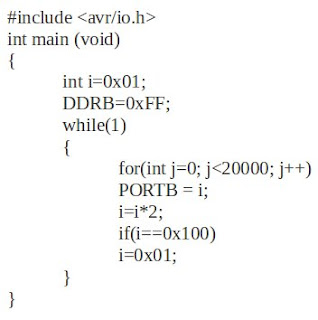
We often see flashing of LEDs in a series which give an effect of running light from one LED to other, when it is kept in a line.  The program below realizes this task.  It needs only a different logic with no new commands other than we discussed.  Now let us think about the logic working behind this program.


Here we are using a property of binary numbers.  The series given below gives the basic idea.


In the 'Result' part we can see the position of '1' is transfered to the left by a single bit position, in adjacent steps.  In the 'Process' part result of the above process is multiplied with '2' to find the new result.  It is logical to represent the whole calculations through the following equation.

i=i*2      where 'i' is an integer variable

The value of 'i' is updated each time the statement executes.

Now let us think about the real situation with LEDs.  Consider the 8 bits in the 'Result' part represent the data in 8 pins of B Port, which is connected to 8 LEDs.  It is interesting to see that the output obtained now was our aim.

Now going back to the logic part.  Since 'i' is an integer variable, its value will increase greater than 0b10000000, if the process continues.  But we have only 8 LEDs connected.  So if the value reaches 0b10000000, it needs to be reset to 0b00000001 to restart the operation.  Thus LEDs will flash continuously.

It is time to think about program coding.  The value of variable 'i' (declared as integer) is set to '1' initially.  There is no need to discuss about the functioning of each statement since we are familiar with all of them in previous sessions.
Here also a 'for loop' is used to obtain the desired delay in between flashing of each LEDs.  Since the value of 'i' represent the Result part in the series, 'i' is directly copied to PORTB.  Because Result part is the desired output.  After having the desired delay, value of 'i' is updated through the equation: i=ix2.  An 'if condition' is given to limit the value of 'i'.  When 'i' reaches 0b10000000, it is reset to 0b00000001 which enables the program to work from the beginning of the cycle.

Many kinds of logics can be developed like this to make different patterns.  Another program producing a different pattern is given below.  The changes in this program from the previous program are colored red.  Readers can dig into it and find the output.


As my friend asked last day, Is blinking LED is the only function of these costly microcontrollers?  The answer is a big 'no' with a small 'yes'.  The matter of fact is that microcontrollers can only generate these kind of small signals having a voltage ranging around 5V with a little mA current.  We need additional circuit arrangements to do other physical needs.

For example, if we need to drive a motor, we need a motor driving circuit.  This circuit is fed by the microcontroller signal to know the rotating direction of motor.  The power for driving the motor is given to the circuit separately.  Now we can understand the functioning of a fully automatic washing machine.  Its different motors are rotated at different timings, at different speeds and at different directions.  All these functions are controlled by processors and hence we say it has 'artificial intelligence'.  We can compare our processor to the brain of a human body.  It produces signals to organs and physical work is done by the organs.  However the possibilities of AVR microcontrollers are beyond limits.  It gives many more facilities in a ready-made package to make the programming simpler.  Let us discuss about them in the upcoming sessions.
Tuesday, January 4, 2011

Session 3 - Automatic blinking LEDs

We are going to achieve something more interesting in this session.  In the first session, the blinking of LED was out of our control.  In the second one, it was in control of switches.  Now controlled, automated switching is going to happen.  Here no need to connect any switches as in the previous case.  Just connect all the pins of B Port to 8 LEDs.  The aim of this session is to prepare a program which can make the LEDs blink automatically for a nominal time interval.  The following program does this job:


Most of the commands in this program are familiar through the previous sessions.  A new comer is the 'for' loop. 'For loop' is a very effective looping tool which can be used in variety of situations.  Here we have used this loop to acquire a delay between the blinking of LEDs.  Let us discuss how this task is accomplished by 'for' loop.  The syntax of 'for' loop is a little lengthy.  It looks like shown below:

From the first look, we can see a control variable named 'j' as main actor in this loop.  Inside the 'for loop', there are three parts.  The first one is familiar in the previous programs.  That is: 'int j=0'.  This statement assigns value '0' to the variable j.  The working of the loop depends on the value of this variable and so it is called the control variable.  The next part is the condition part.  Here it is 'j less than 20000'.  Compiler checks whether the value of the variable 'j' is less than 20000.  If it is true the statements written under the for loop statement will be executed.  (In this case, the value of 'j' is declared as zero.  So the condition is true).  Here the statement written under 'for loop' is PORTB=0x00;.  After executing this statement the third part of the 'for loop' statement will work out.  Here the third part is: 'j++'.  This statement tells the compiler to add one to the value of j.  That is, the statement PORTB=0x00 is executed once and the value of 'j' is incremented to '1' from '0'(0+1=1).  Then the condition is checked again (j less than 20000).  This cycle will repeat until the condition become false (Here when j=20000).

So let us think about the advantage of using this looping statement.  We could execute the statement PORTB=0x00 for 20,000 times without writing 20,000 commands!  We can include more than one statement below the for loop statement by using an opening and closing braces ({}), in the starting and ending of the statements below the 'for loop' statement.

Now let us come to our program.  Why do we need to execute the same command (PORTB=0x00) for 20,000 times?  When this statement is executed once, all the pins of 'B Port' will be in logic 0.  If we execute the statement 20,000 times repeatedly, there is no remarkable change in the output value.  Then why do we need to do this?  The answer is 'Delay'.
We may get a more clarified answer by looking at the next command.  It is another 'for loop' which executes the statement 'PORTB=0xFF'.  When this statement is executed, all the pins of 'B Port' will become logic 1.  And this is again repeated 20,000 times.  Now let us assume that the compiler will take one second to execute the same command for 20,000 times.  If it is so, the logic value of the pins will be altered between 0 and 1 in an interval of 1 second.  The result is: LEDs connected to these pins will be turned on and off in 1 second interval.  Here 1 second is assumed.  Time can be adjusted by calibrating the limiting value of variable 'j' with the output.

Concatenating programs with real time can be done accurately by doing some theoretical calculations.  It is related to the clock frequency of the processor, the time taken by the processor to execute each instruction cycle, etc.  Anyway we can discuss those matters later and now it is desirable to do a calibration technique to achieve one second time delay.

Output of this program is the automated blinking of LEDs in desired time interval.  Thus we have reached our target.  In upcoming sessions we can step further.

Thursday, June 24, 2010

Session 2 - Flash LED on Press of Switch


Now it is time to think about flashing LEDs on the press of switches.  The connections can be done like  8 pins of PORTA to 8 switches and 8 pins of PORTB to 8 LEDs.  The switches should be arranged in such a way that when it is pressed, a high voltage should be shorted to the other end.  The connection of LED is as in the previous session.  Our aim is to turn on the  LED when the respective switch is pressed.  That is, when we press switch 1, LED1 should flash and so on.  This can be achieved by writing a very simple code as shown below:


Program-2

Code Explained:

The code can be understood almost completely by a simple look on it.  However I am going to explain it a little.  Here our code starts with some initialization of PORTA and PORTB.  First PORTA is defined as input (DDRA=0x00;) and then PORTB as output (DDRB=0xFF;).  This time we have used the Hexadecimal format for coding.  Always keep in mind that each digit in HEX format represent 4 binary bits.  So here 0xFF means 0b11111111.

The next code used here is the 'while' loop.  I dare to explain what is a loop.  However, as its meaning indicates, it is a code used for repeated works.  What we write inside a loop, will be repeated.  The question is how much times should it repeat?  In this program the code used is 'while(1)'.  What does this '1' inside the brackets indicate?  Actually a condition is expected at the place of this '1'.  The loop will work on the basis of the result of that condition.  The result can attain two values: True (1) or False (0).  If the answer is a True then the codes written under the loop will work.  As the name of the loop is 'while' its meaning can be predicted.  That is, WHILE the condition is true, the code inside the loop will work.  Or in other words, the codes will work repeatedly until the condition become wrong.  For example take a look at the code below:

a=1;
while(a <= 10)
{
PORTA=0xFF;
a=a+1;
}

This code will work repeatedly for 10 times.
Now let us come to our example.  We have given a '1' instead of a condition and it means a TRUE result always.  Hence this loop always gives true result and the codes inside it will repeat infinitely!  This is what is called an infinite loop.  Infinite loop is an important concept in embedded programming.  We use it in many situations.

Now think about the code written inside the infinite loop which is going to be repeated infinite times (The term infinite means the time, from the processor is turned on and till it is turned off).  It is 'PORTB=PINA'.  This is the first time we use this code 'PINA'.  When a port is used as input, we use the keyword PIN to represent it.  If it is an output we use PORT.  Here the B port is used as output and A port as input and hence PORTB and PINA.  So what does this code do?  It just copies the value of PINA to PORTB.  If we press the switch (connects to HIGH value) connected to the 0th pin of A port (PA0), that value will be copied to PORTB.  So the result is when we press 0th swtich, 0th LED will flash.  When 1st switch is pressed 1st LED will flash and so on.  Since it is inside the infinite loop, the value of PINA is copied to PORTB continuously.  Thus we have reached our target!

Wednesday, June 9, 2010

Session 1 - Blink LED - A Convention

As convention, we can start with a program which blinks LED connected to the processor. The program below does this job. The LEDs should be connected in such a way that when a High Voltage (5V) is connected to one terminal, it should turn on.  It will be very simple to use a development board like STK500 for simulating the program.  (If you are using STK500, its circuit arrangement is different.  It will flash the LED when a zero is fed.)


Program - 1

This simple program can turn on 8 LEDs connected to 8 pins of PORTA of the processor.  The pin names are PA0, PA1,.... PA7.  When you burn this program into the processor, the LEDs will be turned on.  There are a lot of things to be understood behind the working of this program.  We can go to it step by step.

#include...:
Here the statement #include.. is what is called the 'Header file'.  As its name indicates, it is the head of this program.  We include this head in the starting of program.  Because it contains informations about the 'commands' which we use in program.  In that header file, instructions are provided to the computer (or specifically Compiler) about the things-to-do when a command is executed.  There are lot of header files are available.  These are also called as Library files.  Depending on the variety of commands we use in the program, more header files are to be included.  Because all commands cannot be defined in a single header file.  In this program only one header file is enough and that is the one we included here - io.h. io stands for input-output.

int main()
Every C program contains this statement.  The execution of commands will start from this 'main' block.  What we write under this statement will be executed line by line when the program runs.  The two brackets - () can be called as function.  So here we will call it as Main function (main()).  The main() is isolated from other part of the program by providing braces ({}).

DDRB=0b11111111;
Now we are getting into the core of this program.  In this statement, a number is shown as '0b11111111'.  The first two digits - 0b, only indicates that the number following it is in binary format.  If you need to write the number in hexadecimal you can use the prefix '0x'.  If you need to use decimal itself, no need of any prefix.  Usually in programs we follow the hexadecimal format.  It is mainly because the processing of Atmega processors are done in Hex format.  So if we are using hexadecimal, we will feel that we are working very close to the processor.  So this code can be rewritten as:
DDRB=0xFF;
Now what does this DDRB mean?  DDR means the Data Direction Register.  That is the name given by Atmel.  We are going to look on it from our way.  Our aim is to make the processor communicable with the outside world.  For that purpose a lot of pins are provided in it.  What can we do with these pins?  It is to be noted that all logics are realized, through the two states of these pins.  The 'Zero' State and the 'One' State.
When we use an Air conditioner, we adjust the temperature by simply pressing desired switches.  When we press one switch, it will pass a one/zero to the desired pin of th we wante microcontroller.  The program is coded in it such that if a one/zero is received in that particular pin, its meaning is to change the temperature.  For that purpose the processor change the state of another pin which is connected to the temperature control unit of the Air conditioner.  This is what is actually happening in the base level.
In this example of Air conditioner, you can notice one difference in the type of signal.  When we press switch to change the temperature, a signal is given TO the processor.  When processor identifies that it is the signal to change the temperature, we receive signal FROM the processor.  So there are two functions for the pins.  One is to receive input from the outside world and the other is to give output to the outside world.  That is a pin can be used in two ways depending on its direction of flow of signal.  For that purpose we use the DDR - The 'Data Direction Register'.

In Atmega16/32, there are 32 input/output pins are available.  These are divided as PORTA, PORTB, PORTC and PORTD.  In our program the code is written as DDRB.  It represents the pins of PORTB.  The value in this register (Register is a memory space.  Here it contains 8 bits) determines which pins in PORTB are to be used as input and which are to be as outputs.  In this case the value of DDRB is declared as 0b11111111 (8 Bits).  It means all the pins (PORTB has 8 pins) are used as output.  For making these pins input, the value 0b00000000 can be used.  We can make some pins as inputs and some as outputs in a single PORT by adjusting this value.  1 defines an output pin and 0 defines an input pin.

We made all the pins as output because we are connecting LEDs to these pins and our aim is to turn on these LEDs.  So it is an output from the processor.

PORTB=0b11111111;
We have defined the direction of pins as outputs.  Now it is time to think about what values those pins should actually give.  As per the circuit, we need a HIGH (1) output to turn the LED on.  For that purpose the command PORTB=0b11111111 is used.  Here the value 1 will provide a HIGH (about 5V) output in that pin.  So the code here says the processor to make all the pins to HIGH Value.  So when the processor gets turned on, all the pins in PORTB will provide a 5V output.

That's it!  A working program is ready now!  Now a little bit more.  Beginners may feel a main difference between the programs in embedded C and normal C and it is, we do not have a start and stop in embedded.  The program is expected to be working whenever the processor is ON.  But in the case of normal computer programs, we are expected a start and a stop of the program.

Note:  The program can be simulated using the software AVR Studio which can be downloaded from the site of Atmel for free.  The complete details about installing tools, using AVR Studio for creating, compiling, debugging program etc. can be downloaded by clicking here.  It gives a step by step and complete information needed to work with the softwares.

Sunday, February 28, 2010

Let's Begin

Here I am not planned to give an explanation about the basics of microcontrollers and programming languages assuming that you have came here to learn the programming after knowing about what is microcontroller and what is programming. Here I am going to follow the simplest and effective way of learning programming. Without describing about the basics of C programming language like functions, expression, statements, data types, operators, variables, object oriented programming etc. etc., I am directly going to programs and explain them. I leave that burdens of basics to those 'bible' books (or should I say 'classic'?). You can refer those for clearing doubts. Here I have a quick solution for learning embedded C programming that's what everyone need.

As convention we can start with a program that flashes LED. We will go through the different features of AVR microcontroller like Timer, Interrupts, USART, PWM, ADC etc. in a step-by-step manner. A thorough knowledge on these basics will give power to realize any kind of logics.